


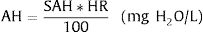
The objective of this study was to evaluate the effects of three single-limb heated wired circuits (SLHWC) for NIV, on ventilatory parameters and humidification performance in a simulation lung model.
MethodsThree SLHWC compatible with the MR-850 Heated Humidifier (HH) (Fisher & Paykel, Auckland, New Zealand) were tested: RT-319 (FP) (Fisher & Paykel, Auckland, New Zealand), Respironics 1045770 (RP) (DEAS, Castel Bolognese, Italy) and Intersurgical B/SYS 5809001 (IT) (Intersurgical, Wokingham, UK). A Bipap Vision ventilator (Philips Respironics, Murrysville, PA, USA) in pressure control ventilation (PCV) connected to a test lung was used for simulation. Each SHWC performance was evaluated in four ventilatory conditions: IPAP of 15cmH2O with FiO2 0.3 and 1, respectively; and, IPAP of 25cmH2O with FiO2 0.3 and 1, respectively. EPAP was set at 5cmH2O. Hygrometric and ventilatory measurements including: relative humidity (RH), temperature (T), Pplat, PIP, PEEP, peak inspiratory flow (PIF), and tidal volume (Vt) were measured.
ResultsIn each FiO2 group absolute humidity (AH) was similar with FP regardless of the IPAP level employed compared to IT and RP (P<.001). Except for RP at FiO2 0.3, AH increased significantly in IT and RP groups as IPAP increased (P<.001). PIP, Pplat, PEEP, PIF, and Vt values were significantly higher with FP and RP in each FiO2 group compared to IT (P<.001).
ConclusionsHumidification performance varied significantly among the three circuits, being FP the only one able to maintain stable AH values during the study with no influence on ventilatory parameters.
El objetivo de este estudio fue evaluar los efectos de 3 circuitos de ramal único (SLHWC) para la ventilación mecánica no invasiva (VNI) en los parámetros de ventilación y la humidificación en un modelo de simulación pulmonar.
MétodosSe evaluaron 3 SLHWC compatibles con el humidificador calefactado MR-850 (HH) (Fisher & Paykel, Auckland, Nueva Zelanda): RT-319 (FP) (Fisher & Paykel, Auckland, Nueva Zelanda), Respironics 1045770 (RP) (DEAS, Castel Bolognese, Italia) y Intersurgical B/SYS 5809001 (IT) (Intersurgical, Wokingham, Reino Unido). Para la simulación se empleó un ventilador Bipap Vision (Philips Respironics, Murrysville, PA, EE. UU.) con ventilación controlada por presión (PCV) conectado a un simulador pulmonar. El rendimiento de cada SHWC se evaluó en 4 condiciones ventilatorias: IPAP de 15cmH2O con FiO2 igual a 0,3 o igual a 1; IPAP de 25cmH2O con FiO2 igual a 0,3 o igual a 1. La EPAP se estableció en 5cmH2O. Las medidas ventilatorias e higrométricas incluyeron: humedad relativa (HR) humedad absoluta (AH), temperature (T), Pplat, PIP, PEEP, pico de flujo inspiratorio (PIF) y volumen tidal (Vt).
ResultadosPara cada grupo de FiO2 FP detectó valores similares de humedad absoluta (HA) en comparación con IT y RP (p<0,001), independientemente del nivel IPAP utilizado. Se registró un incremento significativo de la HA en todos los grupos medidos con IT y RP conforme aumentaron los valores de IPAP (p<0,001), excepto en el grupo de FiO2, igual a 0,3 medido con RP. Los valores de PIP, Pplat, PEEP, PIF y Vt resultaron significativamente más elevados con FP y RP en cada grupo FiO2 en comparación con IT (p<0,001).
ConclusionesLa evaluación de la humidificación varió significativamente entre los 3 circuitos, siendo FP el único capaz de mantener estables los valores de HA durante el estudio sin influencia alguna de los parámetros ventilatorios.
Non-invasive ventilation (NIV) is currently the treatment of choice in various forms of acute respiratory failure.1,2 This therapy involves the use of pressurized cold and dry medical gases with the possibility of signs of dryness in the respiratory tract. The effects of the absence of humidification of inspired gases can on the one hand cause the rejection of this technique due to discomfort and, on the other hand, the possibility of atelectasis appearing as a result of respiratory secretion dryness.3 The American Association for Respiratory Care (AARC) recommends active humidification for NIV, as it may improve adherence and comfort.4 Despite the benefits of conditioned gas administration, there is currently no clear recommendation regarding the type of heated humidifier (HH), or the humidification values to be applied during NIV treatment in acute respiratory failure.5 There are many conditions that can affect humidification performance during NIV. The use of different NIV heated circuits and humidification chambers may influence the temperature and humidity of the gases supplied to the patient.6 The ventilatory system can also affect the performance of the HH in relation to the flow generator used.7 Most of the dedicated NIV ventilators are turbine-driven with a better performance in terms of patient–ventilator synchrony and leak compensation compared to intensive care (ICU) ventilators.8,9 Some studies have shown that these turbine-ventilators deliver higher ventilator output temperatures leading to low humidification values compared to ICU ventilators.7,10
There are no current studies about the interaction of HH on ventilatory variables during NIV with turbine ventilators. The use of different single limb circuits may influence the inspiratory flow rate, due to turbulent flow generation inside the circuit. This can affect the amount of gas delivered to the patient and produce asynchronies. The aim of this study is to evaluate the effects of three single-limb heated wired circuits (SHWC) for NIV, on ventilatory parameters and humidification performance in a simulation lung model.
MethodsInstalling the systemFor the experiment, three SHWC, with its specific humidification chamber, were used: RT-319 (FP) (Fisher & Paykel, Auckland, New Zealand), Respironics 1045770 (RP) (DEAS, Castel Bolognese, Italy) and Intersurgical B/SYS 5809001 (IT) (Intersurgical, Wokingham, UK). FP circuit is designed specifically for use with Fisher & Paykel Healthcare humidification systems. It has a 25-mm inner diameter with a spiral heater wire inside to reduce condensate in varying environments, and to provide a low resistance to flow. RP and IT are circuits with an internal diameter of 22mm. The difference between them is that the IT has a linear heating wire inside, while the RP integrates the heater wires into the circuit wall. All of them are compatible with the MR-850 Heated Humidifier (HH) (Fisher & Paykel, Auckland, New Zealand) (Fig. 1). The MR-850 uses a heated pass-over system to add water vapor to the gas flow and has and automatic flow compensation algorithm, able to maintain constant humidity, recording only minor variations related to changes in the gas flow employed.10 All the circuits had an exhalation port piece (Fig. 2).


For simulation, we used a Bipap Vision ventilator (Philips Respironics, Murrysville, PA, USA) connected to a test lung simulator (Adult/Pediatric Demo Lung, Ingmar Medical, Pittsburgh, USA). The lung simulator consists in two-bellows system with an adjustable resistance and compliance, and a standard 15mm ISO connector. We tested a low compliance model with the following simulation settings: compliance, 20mL/cmH2O; and respiratory resistance, 15cmH2O/L/s. A capacitive hygrometer (HygroPalm, Rotronic AG, Bassersdorf, Switzerland) with a high-performance linear probe (HC2-C05, Rotronic AG, Bassersdorf, Switzerland) was used to measure temperature and relative humidity. This system has a very low dead time and is accurate (humidity range: 0 to 100%, temperature range: −40 to 85°C), recording an error of 0°C and no variations over time.11 At the end of each measurement, the tip of the capacitive hygrometer was dried to avoid any possible measurement error. The probe was placed in the distal part of the tube before connecting it to the test lung. During the experiment, we examined relative ambient humidity and temperature using an additional hygrometer (HygroPalm, Rotronic AG, Bassersdorf, Switzerland) connected to a cylindrical probe (HC2-S, Rotronic AG, Bassersdorf, Switzerland, humidity range: 0 to 100%, temperature range: −50 to 100°C). Hygrometric data were stored on a computer using specific software (Rotronic HW4 version 2.3.0.21699, Bassersdorf, Switzerland) to be later analyzed and calculated. Ventilatory measurements were continuously recorded with a respiratory mechanics monitor (FluxMed GrT, MBMed, Buenos Aires, Argentina) and analyzed with a specific software. (FluxView Software, MBMed, Buenos Aires, Argentina) (Fig. 2).
MeasurementsThe study was conducted under conditions of stable environmental temperature and humidity (20°C and 50% relative humidity), which were measured throughout the experiment as a means of control. Measurements of relative environmental humidity and temperature were taken every 5min throughout the various phases of the study. The ventilator was set in pressure-controlled ventilation mode (PCV) with a respiratory rate (RR) of 12breaths/min, rise time (RS) 0.1s, and an expiratory positive airway pressure (EPAP) of 5cmH2O. For each circuit, an exhalation port test was performed to ensure the accuracy of estimated tidal volume and minute ventilation readings, according to manufacturer's recommendation. Each SHWC performance was evaluated in four ventilatory conditions: inspiratory positive airway pressure (IPAP) of 15cmH2O with FiO2 0.3 and 1, respectively; and, IPAP of 25cmH2O with FiO2 0.3 and 1, respectively (Fig. 3). Before modifying ventilator settings, the system was stabilized to achieve the target temperature values of the HH. Under these conditions, we tested the MR using the active compensation algorithm (software 722) and NIV mode. In each of the phases mentioned above, hygrometric and ventilatory measurements including: relative humidity (RH), temperature (T), peak inspiratory pressure (PIP), positive end expiratory pressure (PEEP), peak inspiratory flow (PIF), and tidal volume (Vt) were measured.

We obtained 120 measurements (one measurement each 30s for 60min continuously) in each experimental situation. A total of 1440 measurements were taken. In order to calculate absolute humidity, the following formulae were used11:
where T is the probe temperature in degrees Celsius, RH is relative humidity, AH is absolute humidity and SAH is saturated absolute humidity, both of which are expressed in mgH2O/L.Statistics
Statistical analysis was performed using IBM SPSS 21 software. Descriptive statistics were obtained for all values with the mean and standard deviation. In order to analyze the differences between groups analysis of variance (ANOVA) was used, while the Bonferroni test was employed for multiple comparisons. A Kolmogorov–Smirnov analysis was used to test normality. A P-value of <.05 was considered statistically significant.
ResultsHygrometric variablesWe obtained a total of 144 environmental measurements. Absolute and relative humidity and temperature remained stable throughout the experiment (24.1±0.5°C ambient temperature, 51.3±3.2% ambient RH, 11.3±0.8mgH2O/L ambient AH).
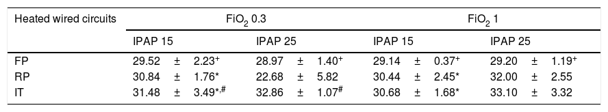
Absolute humidity for the four study groups with different FiO2 and IPAP levels is shown in Table 1. AH was significantly lower in FP compared to RP and IT, regardless of the FiO2 and IPAP level selected (P<.001) (Table 1). In RP and IT groups AH values were significantly higher with a FiO2 of 1 at IPAP level 25cmH2O compared to those at 15cmH2O (P<.001). Fig. 4 shows the evolution of AH with IPAP changes at different FiO2 levels to evaluate the ability of each SHWC to maintain a constant range of values. AH values obtained with FP were similar regardless of the IPAP level employed. In the case of IT and RP, AH values were significantly different for a selected IPAP level of 25cmH2O compared to 15cmH2O (P<.001).
Absolute humidity (in mgH2O/L) of the medical gas with different heated wired-circuits at different FiO2 and IPAP levels. Data expressed as mean and standard deviation.
| Heated wired circuits | FiO2 0.3 | FiO2 1 | ||
|---|---|---|---|---|
| IPAP 15 | IPAP 25 | IPAP 15 | IPAP 25 | |
| FP | 29.52±2.23+ | 28.97±1.40+ | 29.14±0.37+ | 29.20±1.19+ |
| RP | 30.84±1.76* | 22.68±5.82 | 30.44±2.45* | 32.00±2.55 |
| IT | 31.48±3.49*,# | 32.86±1.07# | 30.68±1.68* | 33.10±3.32 |
All data in each FiO2 group was significantly different (P<.001) except for those marked with *, +, #. Key: IPAP=Inspiratory Positive Airway Pressure; FP=Fisher & Paykel RT-319; RP=Respironics 1045770; IT=Intersurgical B/SYS 5809001.
 following a change in IPAP levels at different FiO2. Data expressed as means and CI 95%. *P<.001, IT at IPAP 25 compared to 15; +P<.001, RP at IPAP 25 compared to 15. Key: FP=Fisher & Paykel RT-319; RP=Respironics 1045770; IT=Intersurgical B/SYS 5809001.")
Relative humidity was significantly lower in FP compared to RP and IT (P<.001), except for RP with FiO2 of 0.3 at IPAP level of 25cmH2O (P<.001) (Fig. 5). In the IT group, RH values increased significantly as the IPAP increased regardless of the FiO2 applied (P<.001). The opposite was observed with the FP, with a significant decreased in RH as the IPAP increased with a FiO2 of 0.3 (P<.001). The RH values in RP were significantly higher at IPAP level of 25cmH2O compared to 15cmH2O, when a FiO2 of 1 was set (P<.001).
 following a change in IPAP levels at different FiO2. Data expressed as means and CI 95%. P<.001 for each FiO2 study group between different IPAP levels, except those marked with * in the same study group. Key: FP=Fisher & Paykel RT-319; RP=Respironics 1045770; IT=Intersurgical B/SYS 5809001.")
Evolution of relative humidity (RH) following a change in IPAP levels at different FiO2. Data expressed as means and CI 95%. P<.001 for each FiO2 study group between different IPAP levels, except those marked with * in the same study group. Key: FP=Fisher & Paykel RT-319; RP=Respironics 1045770; IT=Intersurgical B/SYS 5809001.
Fig. 6 displays the behaviour of temperature. In all of the study groups, the temperature raised significantly when the IPAP level increased from 15 to 25cmH2O, regardless of FiO2 selected (P<.001), except for RP group at FiO2 of 0.3 with IPAP of 25cmH2O, where temperature decreased significantly (P<.001).
Ventilatory variables following a change in IPAP levels at different FiO2. Data expressed as means and CI 95%. P<.001 for each FiO2 study group between different IPAP levels. Key: FP=Fisher & Paykel RT-319; RP=Respironics 1045770; IT=Intersurgical B/SYS 5809001.")
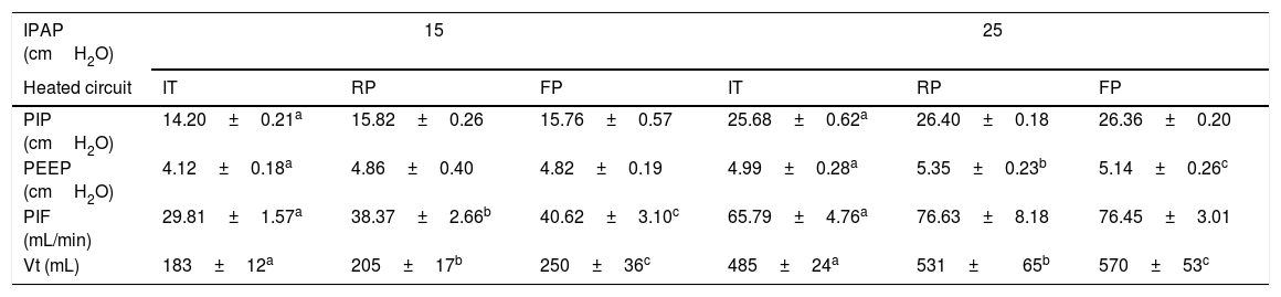
Ventilatory measurements are shown in Table 2. All measurements in the IT group were significantly lower compared to RP and FP (P<.001). At IPAP level of 15cmH2O, a significant increase in PIF and Vt was observed in the FP group compared to RP (P<.001). Measurements obtained at IPAP level of 25cmH2O were similar between FP and RP, except for Vt and PEEP with higher values in the FP and RP, respectively (P<.001).
Ventilator variables values with different heated wired-circuits at different IPAP levels. Data expressed as mean and standard deviation.
| IPAP (cmH2O) | 15 | 25 | ||||
|---|---|---|---|---|---|---|
| Heated circuit | IT | RP | FP | IT | RP | FP |
| PIP (cmH2O) | 14.20±0.21a | 15.82±0.26 | 15.76±0.57 | 25.68±0.62a | 26.40±0.18 | 26.36±0.20 |
| PEEP (cmH2O) | 4.12±0.18a | 4.86±0.40 | 4.82±0.19 | 4.99±0.28a | 5.35±0.23b | 5.14±0.26c |
| PIF (mL/min) | 29.81±1.57a | 38.37±2.66b | 40.62±3.10c | 65.79±4.76a | 76.63±8.18 | 76.45±3.01 |
| Vt (mL) | 183±12a | 205±17b | 250±36c | 485±24a | 531±65b | 570±53c |
Key: IPAP=Inspiratory Positive Airway Pressure; FP=Fisher & Paykel RT-319; RP=Respironics 1045770; IT=Intersurgical B/SYS 5809001; PIP=peak inspiratory pressure; PEEP=positive end expiratory pressure; PIF=peak inspiratory flow; Vt=tidal volume.
During NIV, the absence of medical gas humidification may cause dryness in the respiratory tract. The ideal humidification value to preserve the function of the mucociliary system is 44mgH2O/L, measured after the carina.12 Although, upper airways are not bypassed during NIV, high-flow from turbine-driven ventilators can make physiological gas humidification less effective. These data suggest that the use of humidification systems to condition gas during NIV may be beneficial to prevent respiratory complications.
The performance of the HH can be influenced by several factors, but the main ones are room temperature and gas temperature before passing through the heating chamber.10 Differences in ambient conditions, HH, respiratory circuit, ventilator, and wall gas temperature can influence on the humidity and temperature of the gases delivered to the patient.7,10,13,14 In our study we tested in similar ambient conditions the influence of three different SHWC on MR-850 HH automatic humidity compensation algorithm performance, using a turbine-driven NIV ventilator. Although, the FP circuit had the lowest AH values of the three circuits evaluated, it was able to maintain constant AH values, recording only minor variations related to changes in the IPAP level employed, with no influence from the FiO2 used. In the case of IT and RP, humidification values varied in relation to the IPAP level used, being higher as the IPAP increased, regardless of the FiO2 selected (Fig. 4). One explanation to these results are the differences in the type of chamber and the different heated wired systems between the three circuits. The MR-850 HH in non-invasive mode is programmed to generate theoretical values of absolute humidity of 32mgH2O/L regardless of changes in flow, FiO2 level and, ventilator outlet temperature. This is possible due to the automatic humidity compensation mode that was developed by the manufacturer to optimized HH performance. When the automatic mode is selected the humidifier calculates the power required to adequately humidify the gas flow through the chamber, providing constant humidification values. The humidifier monitors the temperature and gas flow at the chamber outlet with the chamber probe, and the limb temperature with the distal probe. The system controls the amount of power delivered to the heater plate, in order to maintain the chamber's set values of humidity and temperature. In addition, the circuit is heated to achieve a positive temperature gradient of 3°C at the end of the limb. This temperature gradient causes the RH to drop from 100% to 80%, maintaining the same amount of AH and avoiding condensation between the end limb and the mask. For an optimal system performance, it is necessary that the HH recognizes the type of circuit and the humidification chamber used, in order to adjust the amount of energy necessary to produce humidity in the range of values of the compensation algorithm. In the case of FP, the system performed more stable, because the HH was able to automatically recognize the circuit. The expected RH values with the FP circuit were around 80%, as a result of increasing the temperature of the limb in order to avoid circuit condensation (Fig. 5). In the case of IT and RP, RH values were higher showing that the MR-850 automatic compensation mode did not perform as well as with the FP circuit. Although AH with FP were slightly lower than the theoretical values, those were relatively constant regardless of IPAP and FiO2 levels. It is interesting to note that in the case of RP there was a sudden decrease with IPAP level of 25 at FiO2 of 0.3, with a mean AH values of 22.68±5.82mgH2O/L. This can be due to a malfunction of the proximal temperature sensors or a faulty connection between the sensor and the tube, leading to a decrease in the amount of power delivered to the heater plate, with the result of lower humidification values.
Ventilator variablesThe type of respiratory circuit can influence in the amount of gas delivered to the patient. The flow of gas through a tube depends on one hand on the pressure exerted, and on the other hand on the resistance of the tube. In the present study we evaluated three circuits with different resistance to flow. In the case of IT we observed a significant decrease on PIF, Vt and PIP compared to the other two circuits evaluated, in all the experimental conditions. These results can be explained by the presence of a linear wire inside the IT tube that can increase the turbulent flow inside the tube. The precise relationship between pressure gradient and flow rate depends on the nature of the flow which can be laminar, turbulent or a mixture of the two.15 Situations of high flow rates with irregular tubes result in a breakdown of the orderly laminar flow, with an irregular movement superimposed on the general progression along the tube, creating turbulent flow. In mechanical ventilation, with constant gas viscosity, the major determinant of turbulent flow is the inner diameter of the tube so, factors that affect this diameter can influence in the performance of the ventilator. The linear wire of the IT circuit can generate frictional forces between the gas and the tube wire leading to turbulent flow and making the inner diameter irregular. In the case of FP, the higher inner diameter and the spiral heater wire make the circuit less resistant to flow generating more flow with the same driving pressure compared to IT. The same occurs with the RP that integrates the wire in the tube wall, allowing a smooth surface for the gas to flow, and decreasing the generation of turbulent flow.
In a recent bench study, Ferrone et al. evaluated two ventilator circuits during helmet NIV: a double limb circuit (with one inspiratory and one expiratory line) and a standard circuit (a Y-piece connected only to one side of the helmet, closing the other side).16 They concluded that, using a standard circuit, both the inspiratory and the expiratory flows were forced to pass through the Y-piece of the circuit, probably generating turbulence that may increase resistances inside the passage, thus inducing alterations in patient–ventilator interaction. These results highlight the effects of ventilator circuits on respiratory mechanics.
The differences in flow rate between the three circuits observed in our study can influence in clinical practice specially in the presence of patient–ventilator asynchrony. Vignaux et al. demonstrated that asynchronies are common during NIV.17 They reported an incidence of auto-triggering of 13%, and delayed cycling of 23% in multicenter study of patients with acute respiratory failure treated with NIV. Patient–ventilator asynchrony can significantly increase the work of breathing,18,19 and a high incidence of patient–ventilator asynchrony is associated with a longer duration of mechanical ventilation.20 In order to minimized this problem, manufactures have developed dedicated NIV ventilators, particularly oriented towards leakage management and comfort. Some bench studies have observed that dedicated turbine-driven NIV ventilators allow a better patient–ventilator synchrony than ICU and transport ventilators.8,9 The results our study suggest that the type of humidification circuit, beyond the ventilatory settings and leak compensation algorithms, can influence the flow and volume delivered to the patient. In our study, FP and RP circuits have better flow performance compared to IT. The linear wire jointly with an inner diameter of 22mm in the IT circuit may generate turbulence flow specially in situations of increase flow demand or leak compensation, making the ventilation less effective. Due to the use of a passive lung simulator it is not possible to infer directly from the results of the study the possibility of generating flow asynchronies. However, the differences observed in the peak inspiratory flow between the different circuits, with a fixed rise time, give an idea that the behaviour of the inspiratory flow is different as a consequence of variations in the internal diameter of the circuits. The fact that one of the circuits has a greater resistance to flow could influence the synchronization, even if the patient did not present a high inspiratory effort.
LimitationsBearing in mind that this is a pilot study that was performed under ideal conditions, the hygrometric and respiratory values obtained may be different to those obtained in real conditions. Moreover, we evaluated respiratory mechanics in a continuous mandatory ventilation model, and the results can differ from those obtained either in a spontaneous ventilation model or with patients. It is interesting to note that we evaluated normal ventilatory conditions with a RR of 12, that is not usual in patients with respiratory failure treated with NIV, and this can limit our results when extrapolating them in real conditions. However, we think that in clinical conditions the differences between the three circuits, in terms of ventilatory parameters, would be the same, although it would be necessary to confirm this point with clinical studies. Other limitation is related to the ventilator use in our study. This ventilator does not identify the resistances and compliance of the circuit. Newer ventilators can calibrate the resistances and compliance of the circuit and therefore modify the pressurization according to these. This fact could limit the differences in the values identified for each circuit if we had evaluated such type of ventilators.
In our study, we did not evaluate the effect of the nasopharyngeal conditioning system on temperature and humidity, which in real terms during NIV partially contributes to conditioning inspired gas. It is important to mention that ventilatory parameters measurements in our study were obtained under ideal conditions without leaks and may therefore differ to those obtained in clinical practice. It would be necessary to conduct clinical studies to ascertain the impact of heated circuits in patient's respiratory mechanics and asynchronies generation.
ConclusionsThis study is the first to undertake an in vitro evaluation of humidification and respiratory mechanics performance of three different SHWC. From the analysis of the results it can be seen that the type of circuit used, influences both humidification values and ventilatory variables. The FP circuit was the most reliable in terms of two factors combined: stable humidification values independently from changes in ventilator settings and, low resistance to flow tested with the BiPAP Vision compared to the other two circuits. This study suggests that heated circuits can affect humidification and ventilator performance.
FundingThis study was conducted at Centro de Simulación Clínica Avanzada (CESIMAV), Meliana (Spain) and was supported by institutional funds.
Conflict of interestsThe authors declare no conflict of interests.